I don’t really like the breadboarding phase of electronic projects - that’s why I, in 2020, bought a GENMITSU 3018-PROVer. I chose this one because it had pretty good reviews for a tabletop 3018 CNC router in this price range, but I haven’t used it much. Definitely not to make PCB’s.
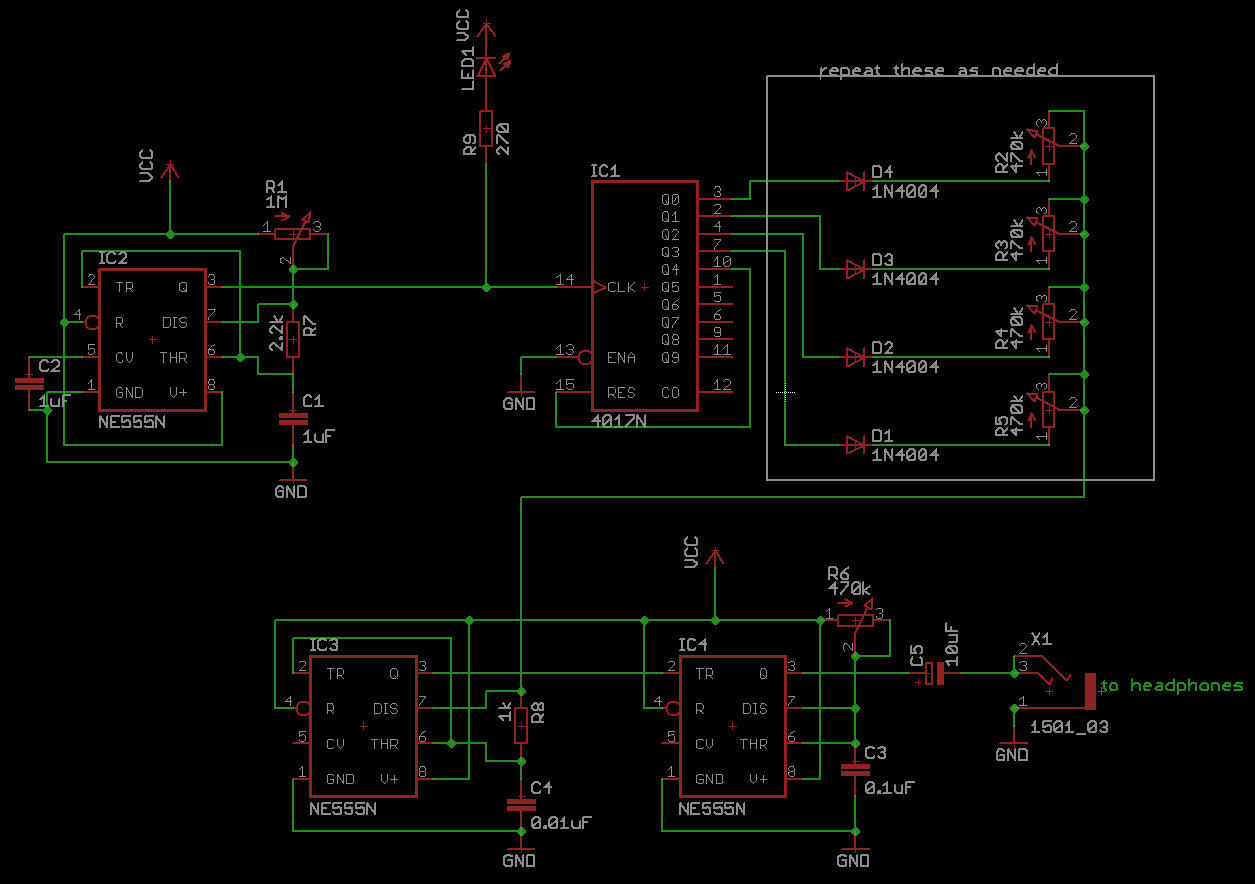
But now was the time. I wanted to start off with a one-sided PCB, but I’m not very good with PCB layouts, so I found this blog post where he creates a Four Step Atari Punk Console as a one-sided PCB. I seemed like a pretty simple project, and in the video it sounds cool as well.
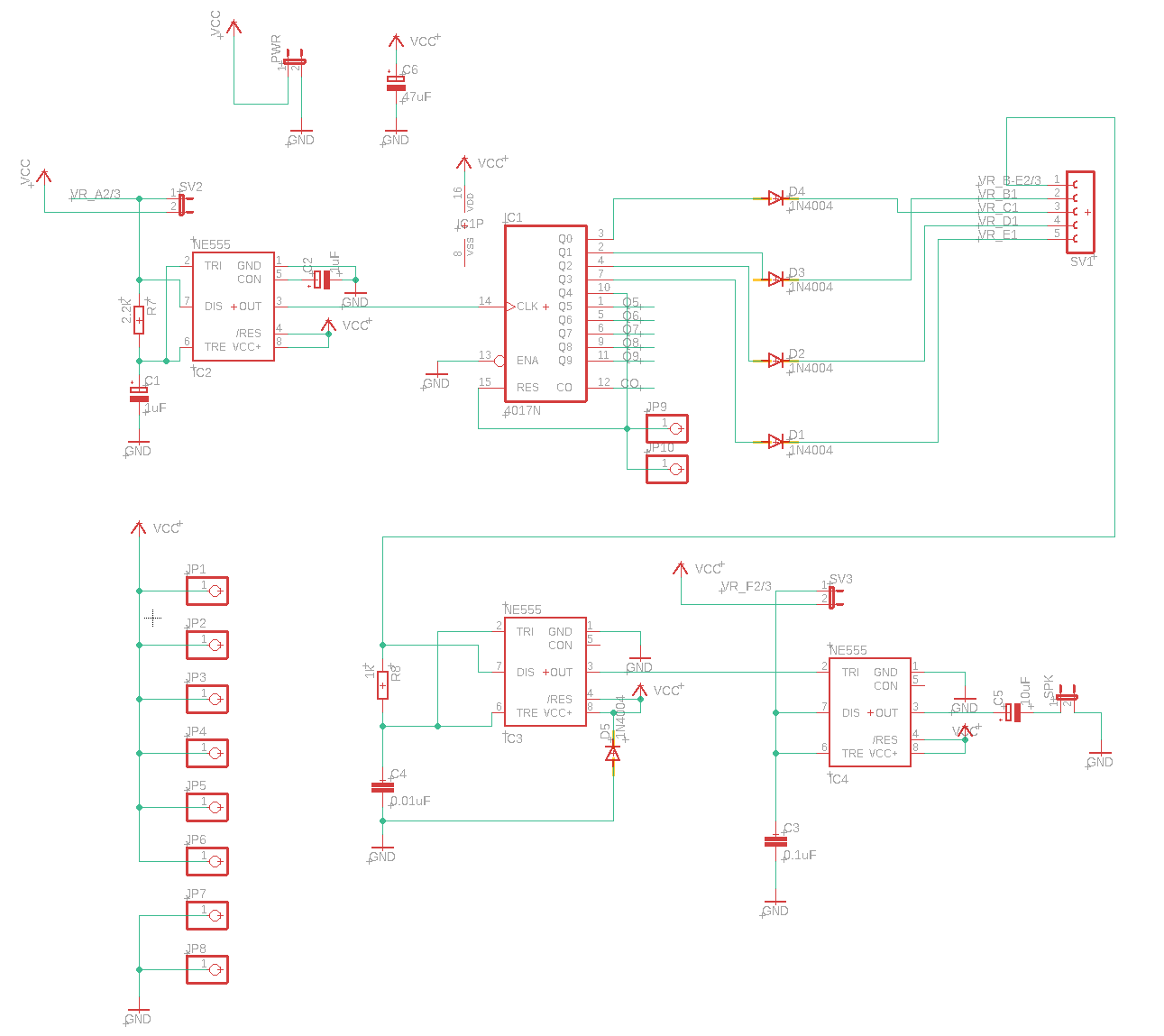
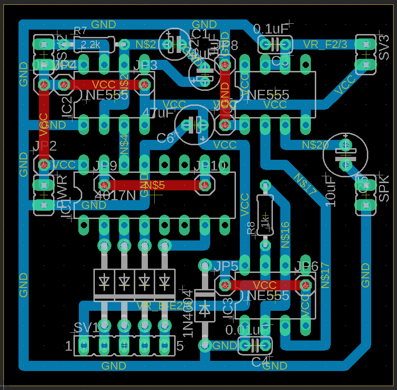
In the comments, he links to schematic, but that link is dead now. Another user found it on the Internet Archive Wayback Machine. I recreated the schematic in Autodesk EAGLE, but there was a capacitor in the layout in the blog post that didn’t exist in the schematic, so I added that. I also needed some solder pads for wires, and for that, I used pin headers. I notice now that I used pin headers from several different libraries, which doesn’t look pretty; my apologies..
On the table of the CNC I put a 6 mm MDF spoil board, and I read online that this should be flattened in order to keep the CNC precise. I did this using a 32 mm surface planing router bit, which was way too big for my machine, as it almost shook itself to pieces. I should probably have filmed that or taken some pictures.
Then I mounted the PCB with double-sided tape, and it was time to make a height map, because apparently they come with imperfections, and this let’s the CNC controller take them into account.
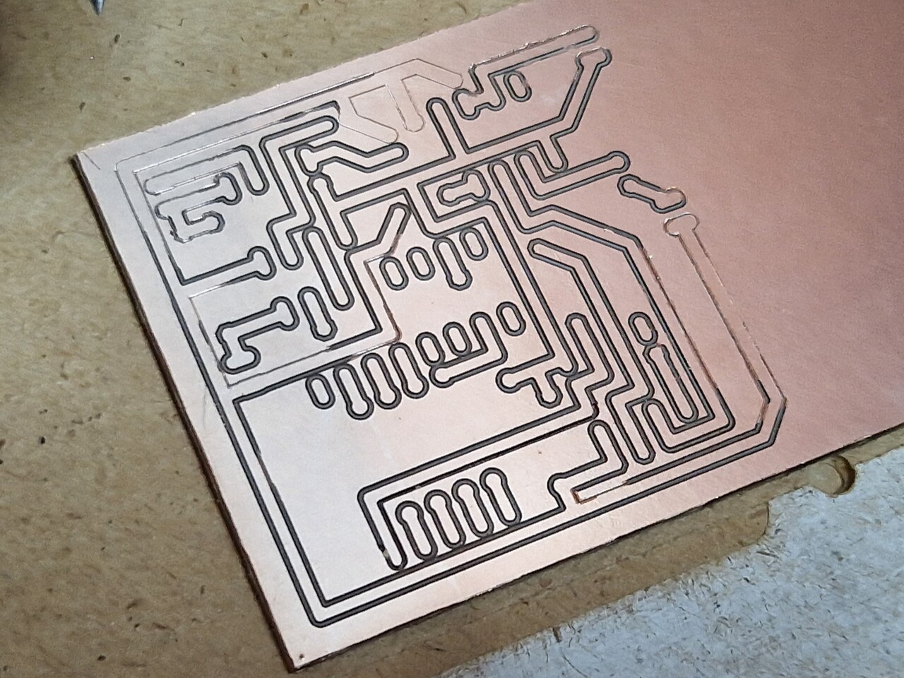
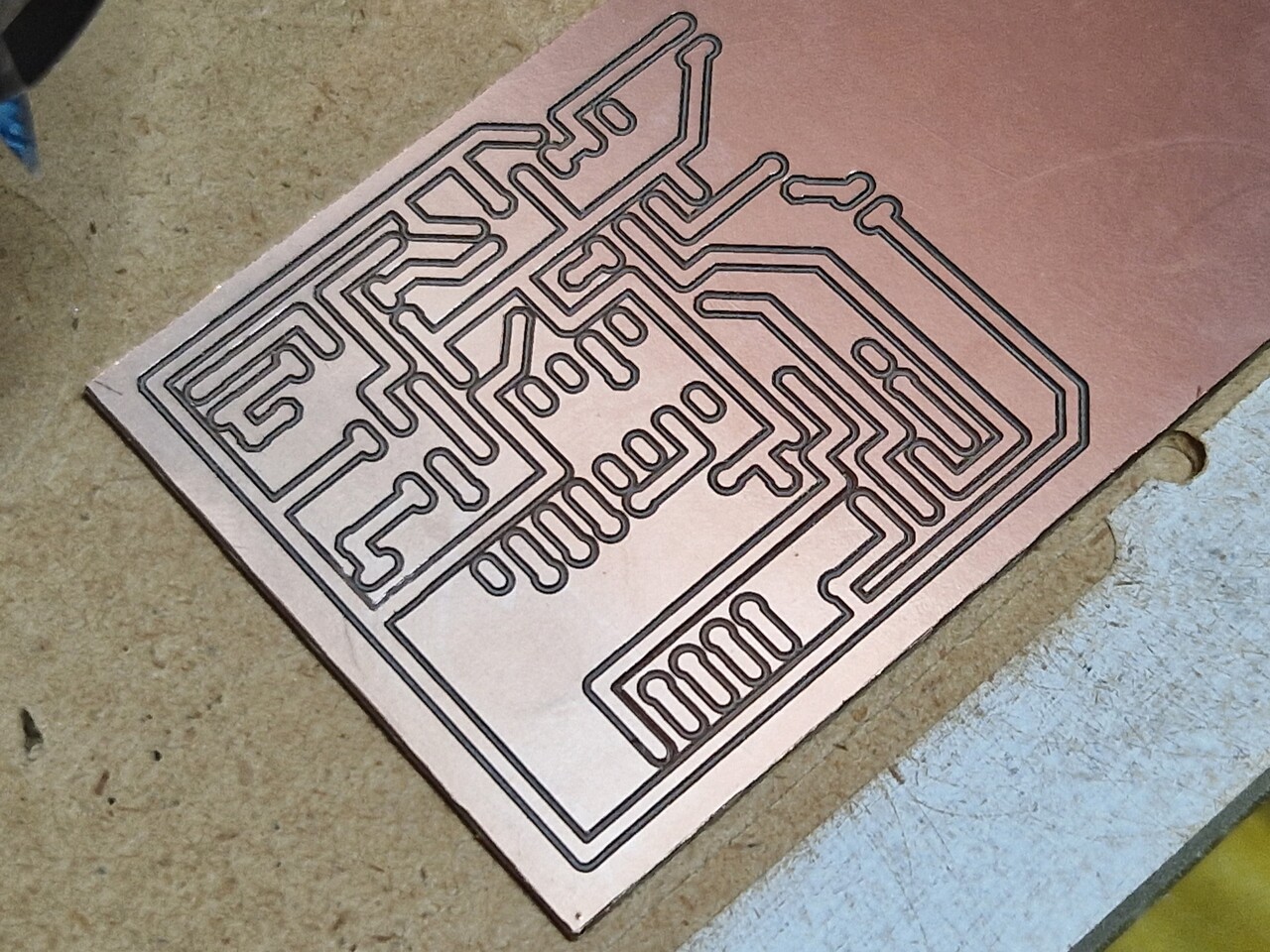
The G-Code was sent to the CNC and it went surprisingly well. I was really satisfied with some super crisp and precise lines, but there were some places where it did not go all the way through the copper. I don’t know if the height map grid spacing should have been smaller, the PCB better secured, the spoil board more flat, or maybe the material under the cobber was uneven - I guess i’ll have to test that out next time. But I ended up running the program 3 or 4 times, increasing the depth 0.1 mm each time, and I think I ended at 0.6 mm.
Note: I just watched my footage while editing the video posted further down, and I noticed that the PCB flexes at the upper left corner when the tool touches it, so I guess that it wasn’t secured surely to the spoil board.
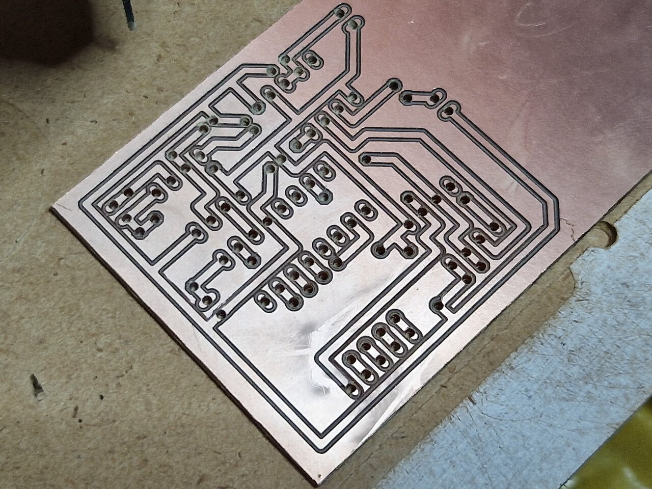
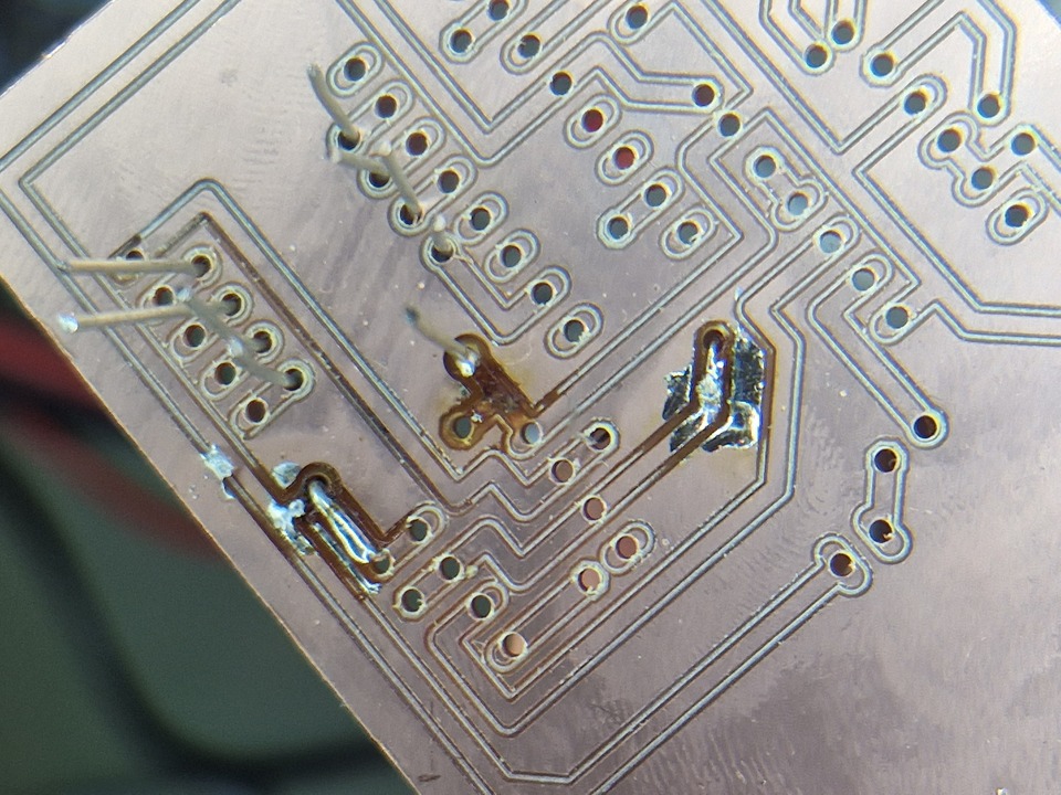
I did not have any drill bits, but I did have a 0.8 mm end mill that I wanted to use. I broke that instantly, and used a 1 mm end mill instead, but that was way too big and resulted in basically no solder pad left to solder to. I tried soldering it anyway though, and in an effort to compensate for the missing solder pads, I applied way too much heat, and the copper started coming off. To rectify that, I tried to bend the legs of the components, but that’s very hard to do precisely. At some point I tested connectivity from the “outside copper” to the circuit and there was connection, and at this point I said “fuck it” and gave up.
I haven’t given up for good yet though. I’ve ordered some drill bits on AliExpress, and as mentioned, I have some ideas for a more successful routing. If I’m more successful in the future I’ll probably make a more in-depth guide. Here are some facts and stats about this project:
- CNC Router: GENMITSU 3018-PROVer
- CNC controller (GRBL): Candle 1.1.7
- PCB design software: Autodesk EAGLE
- CAM software: FlatCAM
- CNC milling bits: 20° V-bit and 1 mm corn cob
- Feedrate X-Y: 120 units per minute
- Feedrate Z: 60 units per minute
- Spindle speed: 10,000 RPM
Here’s a short video of the project, and below that a more detailed slide show: